Achieving Stable Flight in GPS-Denied Environments
featuring position-holding, a gripper, and sensor fusion with optical flow and LiDAR

This UAV was built to compete in the Technology Student Association UAV Challenge. It was built and iterated over the span of three years.
It is capable of holding position in GPS-denied environments using optical flow and LiDAR. It was designed with a modular 3D-printed airframe and servo-actuated gripper to move payloads. It implements EKF sensor fusion, remote telemetry, and power distribution systems.


Photo Log
 | M3 inserts are set into the 3D printed middle plate. The inserts ensure that the PLA can’t strip. |
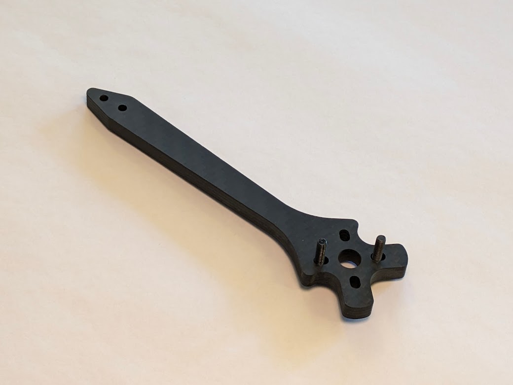 | We used carbon fiber arms instead of 3D printed plastic arms. This change allowed us to customize and expand our frame while retaining the rigidity and durability of a traditional full carbon fiber frame. |
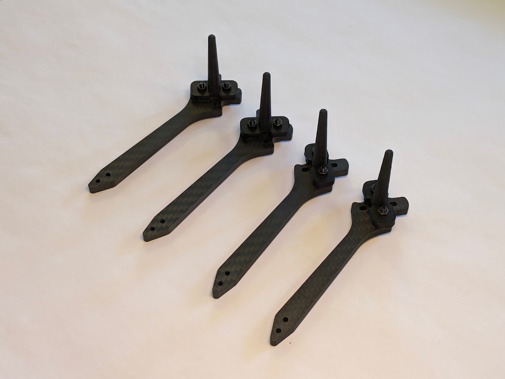 | 3D printed landing gear are attached to each arm. These were used for initial assembly and testing and will later be swapped for more durable landing gear with metal inserts. |
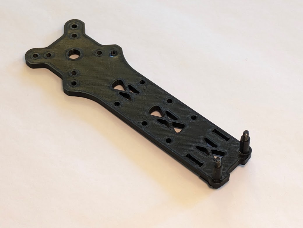 | The bottom plate was also 3D printed for expandability. M3 standoffs were added to the edge for later construction. |
 | Components start to get screwed together. |
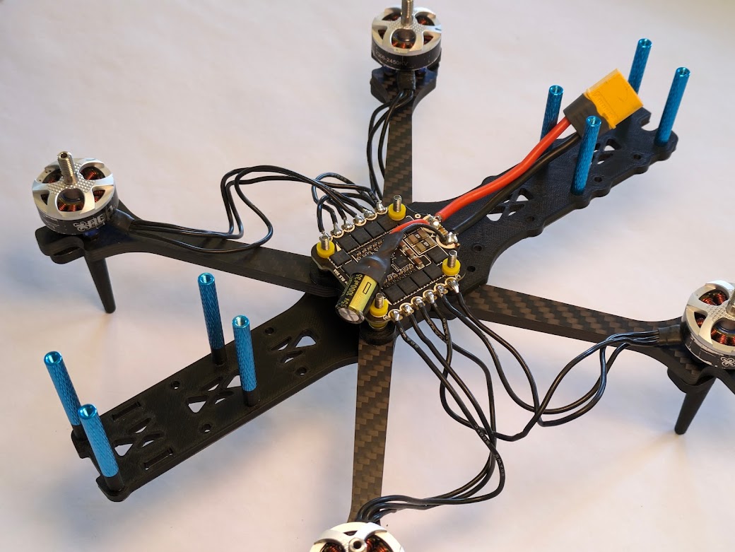
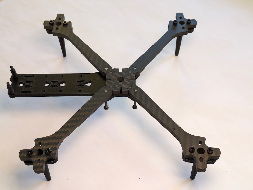 | The arms are mounted to the bottom plate. The center brace is also made of carbon fiber for better horizontal rigidity. |
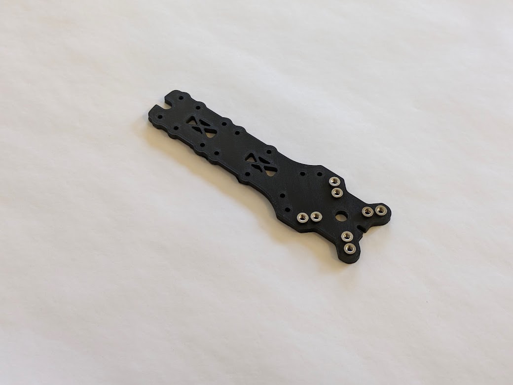
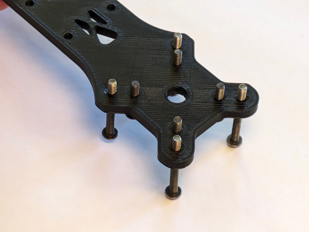
 | The top plate is attached to the chassis. The four protruding screws in the center are where we will mount the flight controller (FC) and electronic speed controller (ESC). |
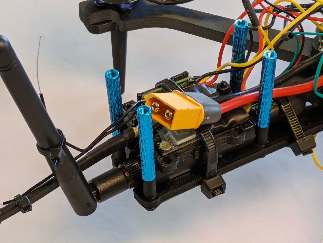
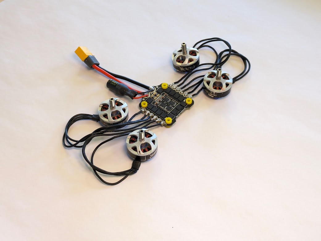 | The motors are soldered to the ESC. The XT60 LiPo connector and a capacitor are soldered to the ESC. The capacitor smooths voltage spikes to prevent brownouts and dirty power for the FC. |
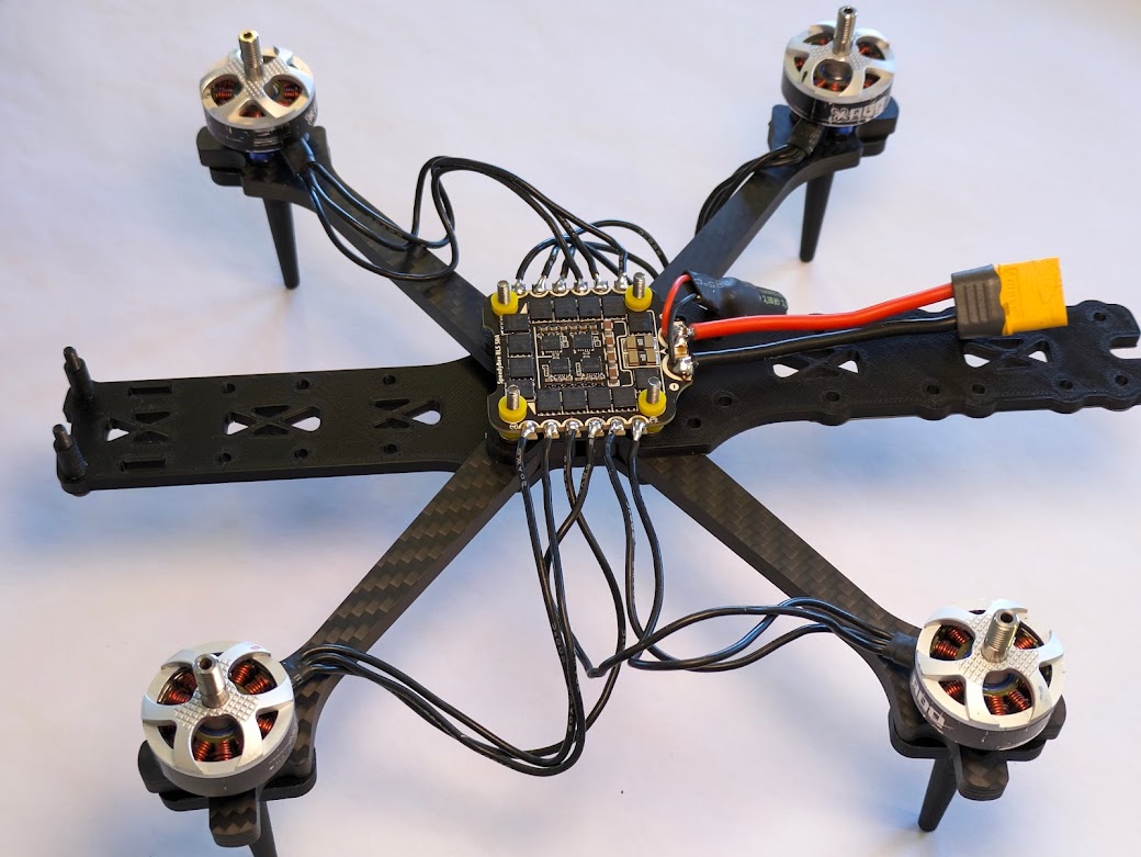 | The ESC is attached to the top plate. The motors are attached to the arms. |
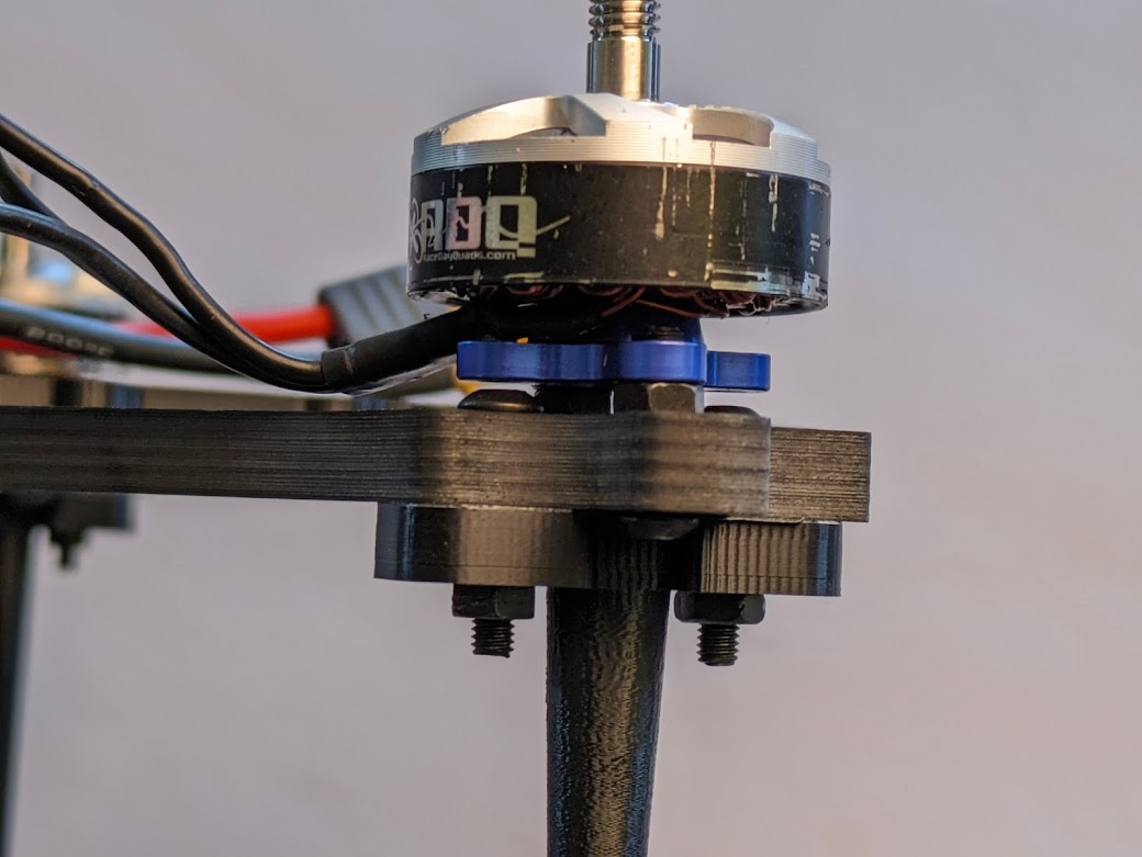 | Each arm has four screw holes on the end. Two are for the motors and two are for the landing gear. The M3 spacers between the motor and the arm allow this to happen. |
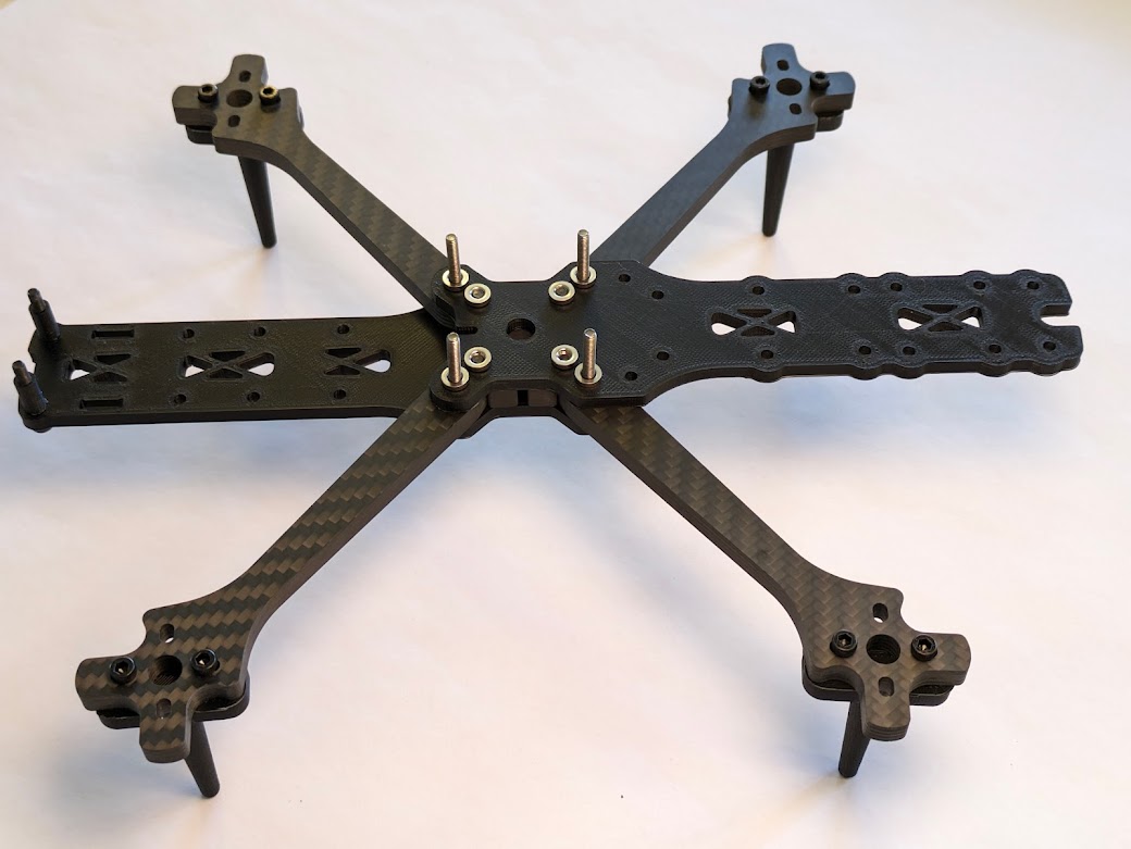
 | M3 space standoffs are added to the chassis plates. Later, the top plate will be attached to these standoffs. |
 | The combined barometer and magnetometer, or compass, is plugged into a custom-soldered wiring harness. |
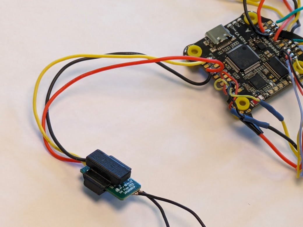 | The XM+ receiver is placed in a 3D printed mount and has wires soldered onto it. |
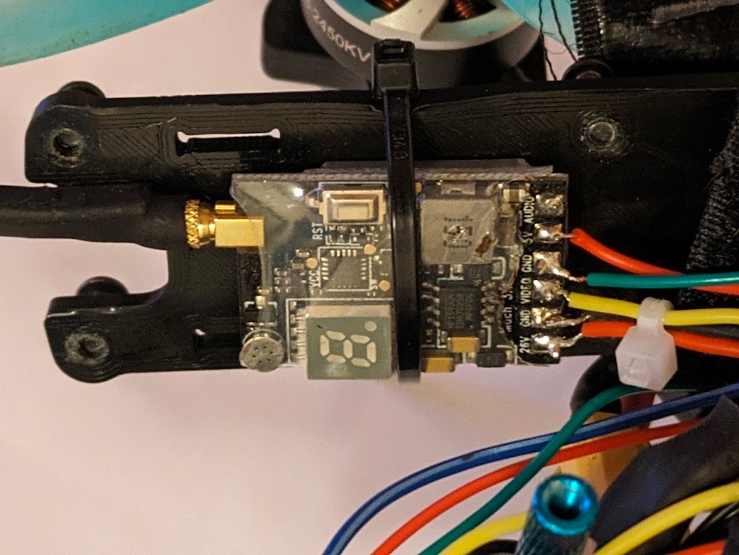
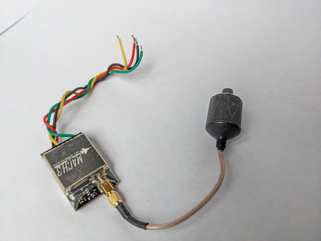 | The RDQ Mach 3 video transmitter (VTX) has wires soldered onto it. |
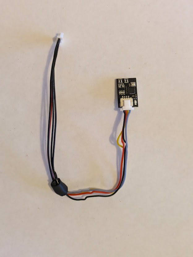
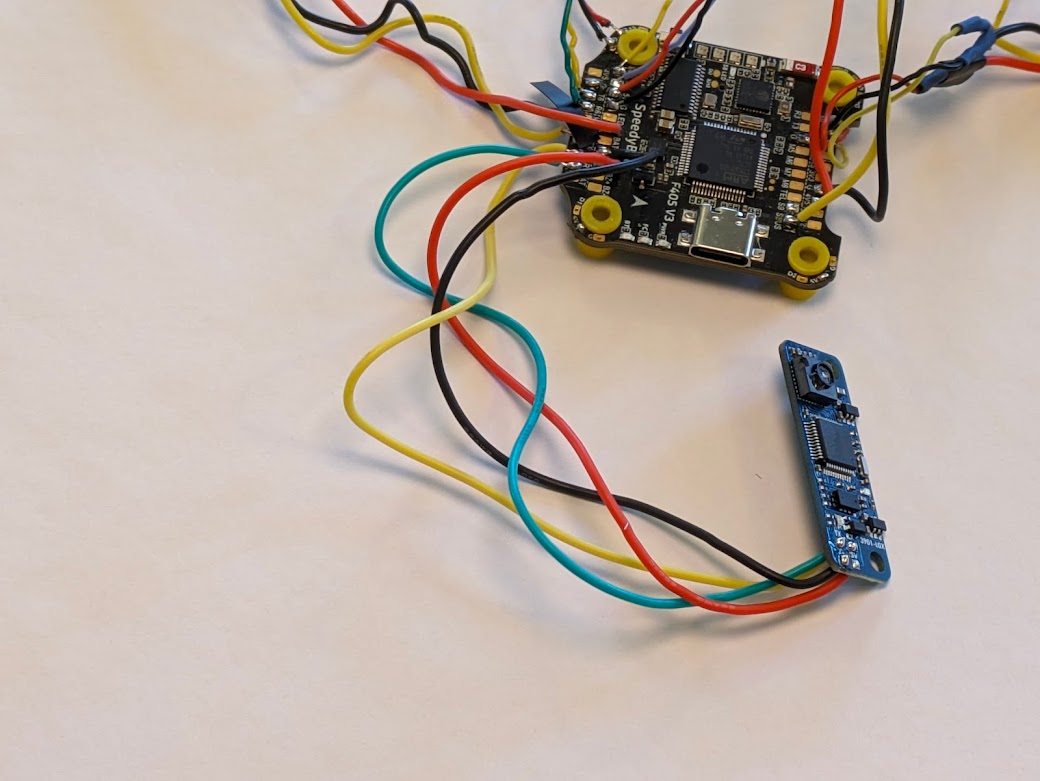 | Wires are soldered onto the combined LiDAR/optical flow sensor. We are only using the optical flow function because the built-in LiDAR sensor doesn’t have a long enough range. |
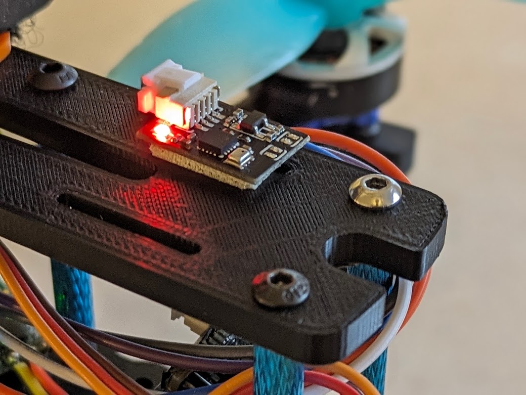
 | The telemetry radio is plugged into a custom-soldered wiring harness. This radio allows wireless configuration of the quadcopter, as well as the ability to see telemetry data in real time. |
 | The telemetry radio and receiver are attached to the bottom plate of the chassis using a zip tie. |
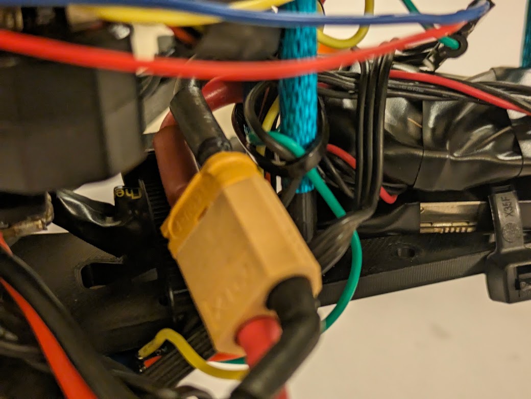 | The power module is attached. This module provides clean power at a standard voltage for the Pixhawk. |
 | The LiDAR/optical flow sensor is attached to the underside of the bottom frame. |
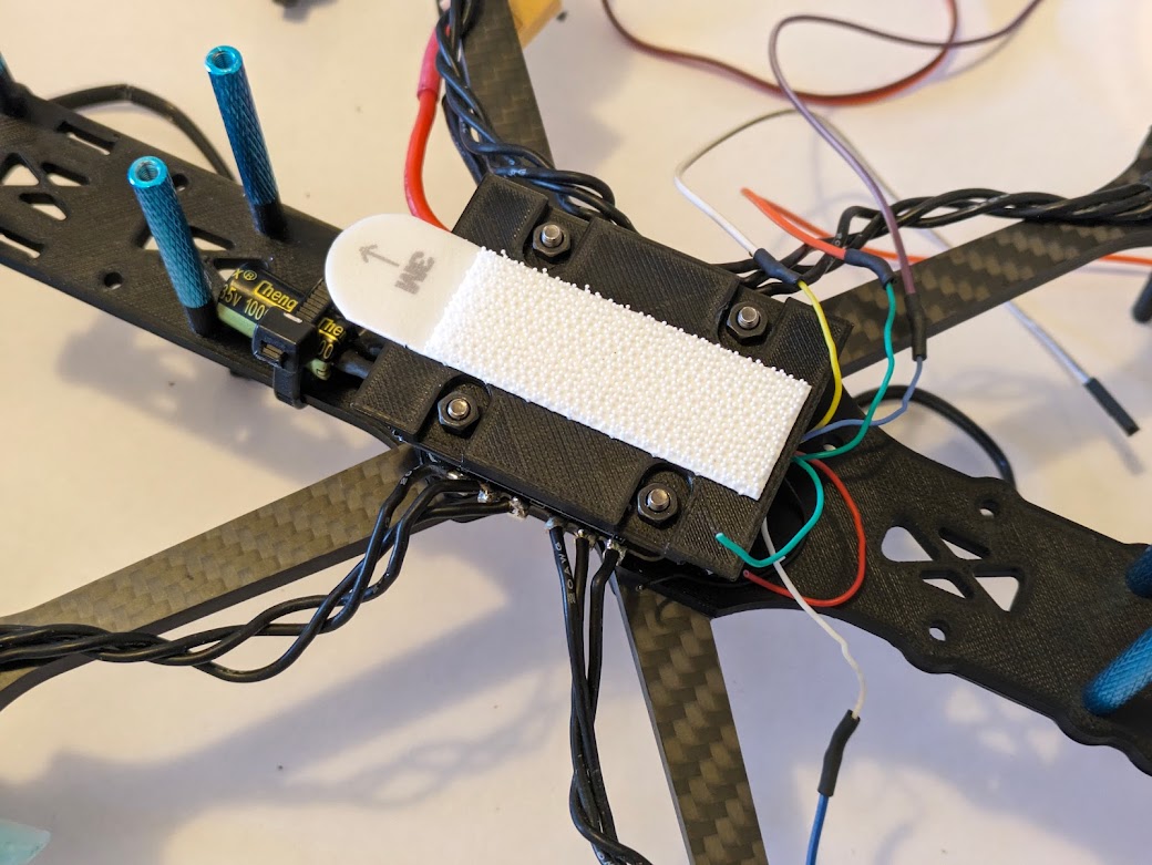 | The custom 3D printed mounting plate for the Pixhawk flight controller is attached to the ESC. With velcro attached, the Pixhawk will hook in place for simple removal. |
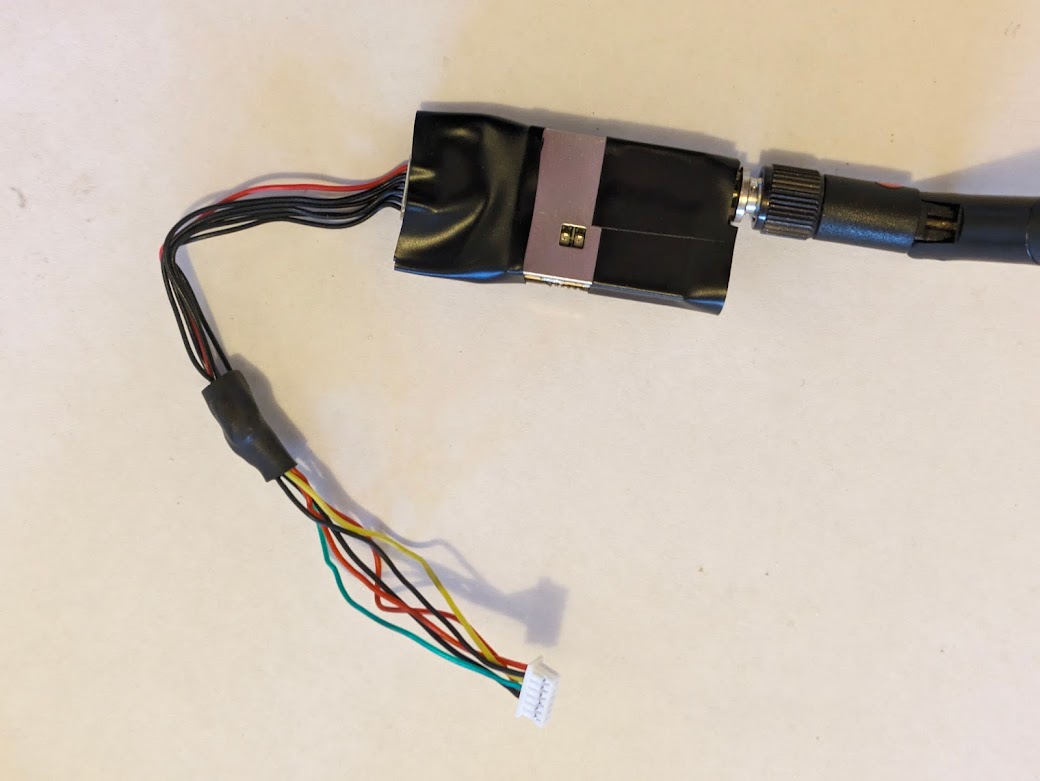
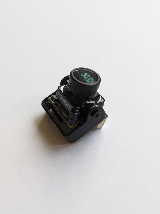 | The camera is attached to a mount that we will then attach to the quadcopter. |
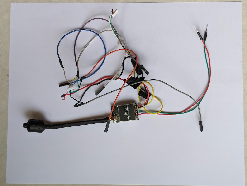 | The wiring system for the video transmitter, camera, and servo motor is soldered up. See more details in the wiring diagram. |
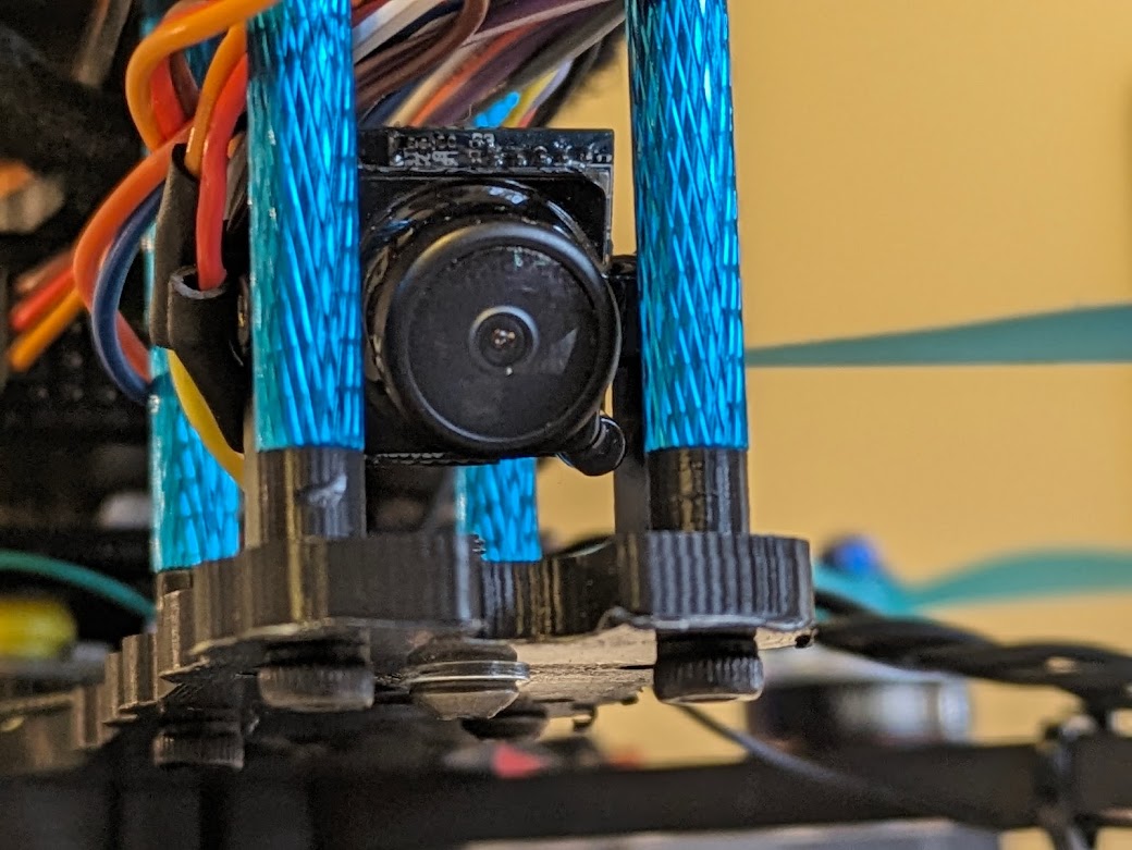 | The camera and its mount are attached to the middle chassis plate. |
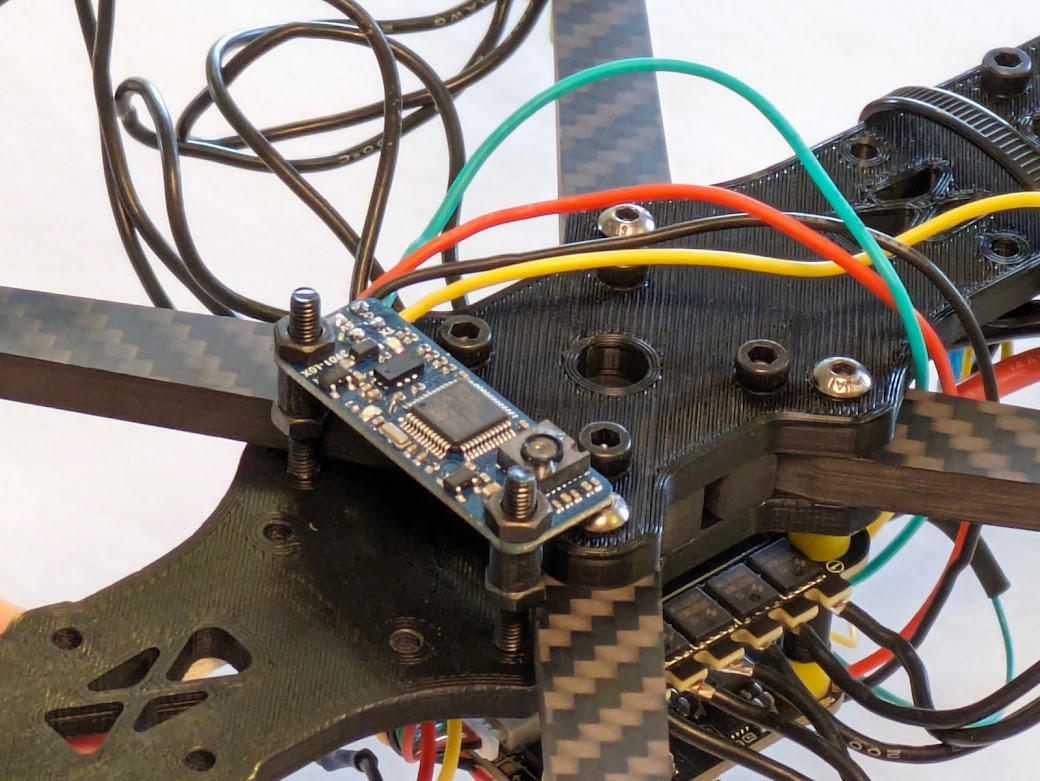
 | The magnetometer/barometer is attached to the top chassis plate. It has been attached far away from large metallic objects and from battery/motor cables to prevent electrical interference. |
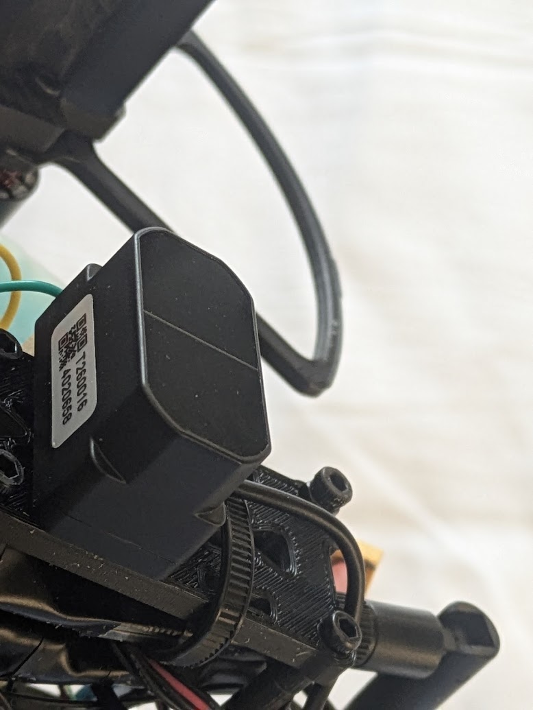 | The external, more powerful LiDAR sensor is attached to the bottom of the quadcopter. |
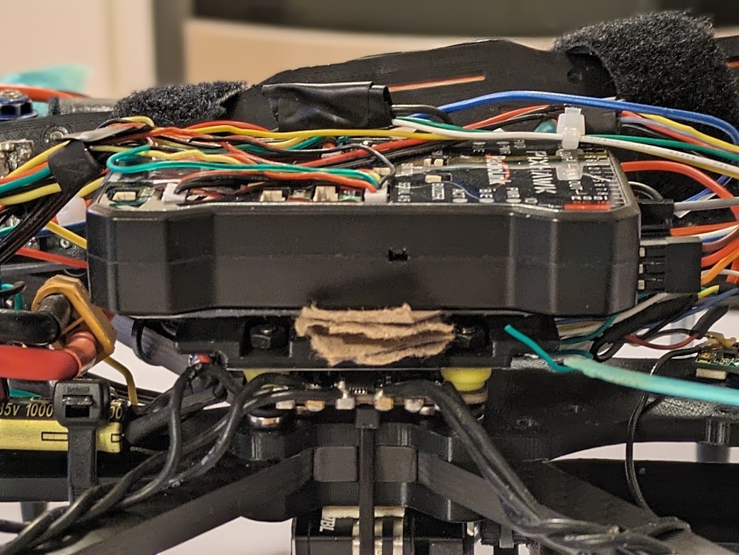 | The Pixhawk is attached to the Pixhawk mount. Cardboard between the mount and the Pixhawk dampen vibrations. |
 | The VTX is zip-tied in place to the top chassis plate. |
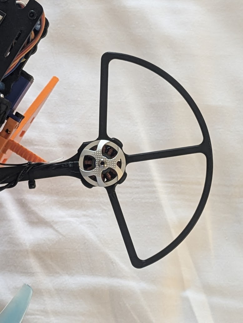 | Propeller guards are attached to the arms. |
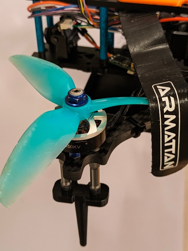 | The propellers are attached to the motors. |
 | We made this new version of the landing gear with metal inserts and screws throughout, improving durability. |
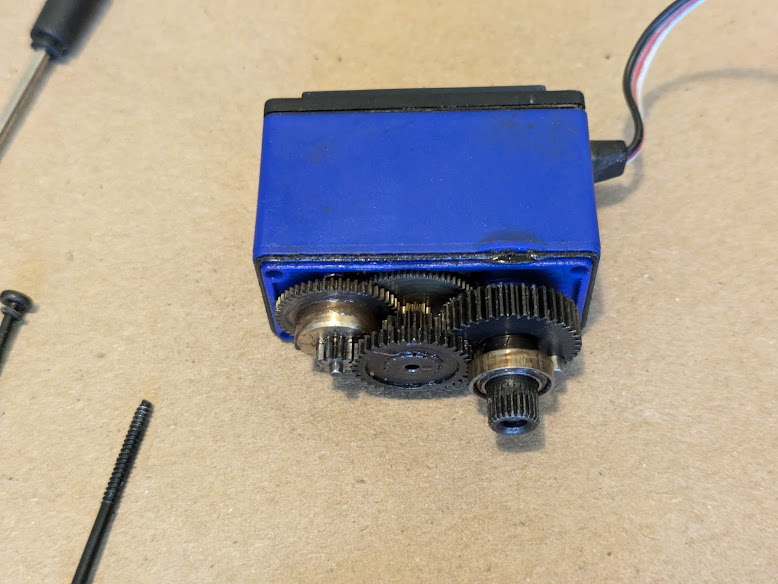 | Typical servos are limited to a total of about 180 degrees. Continuous rotation servos exist, but many are too weak for our use. To overcome this, we have modified a standard servo to convert it to continuous rotation. First, the servo is opened. |
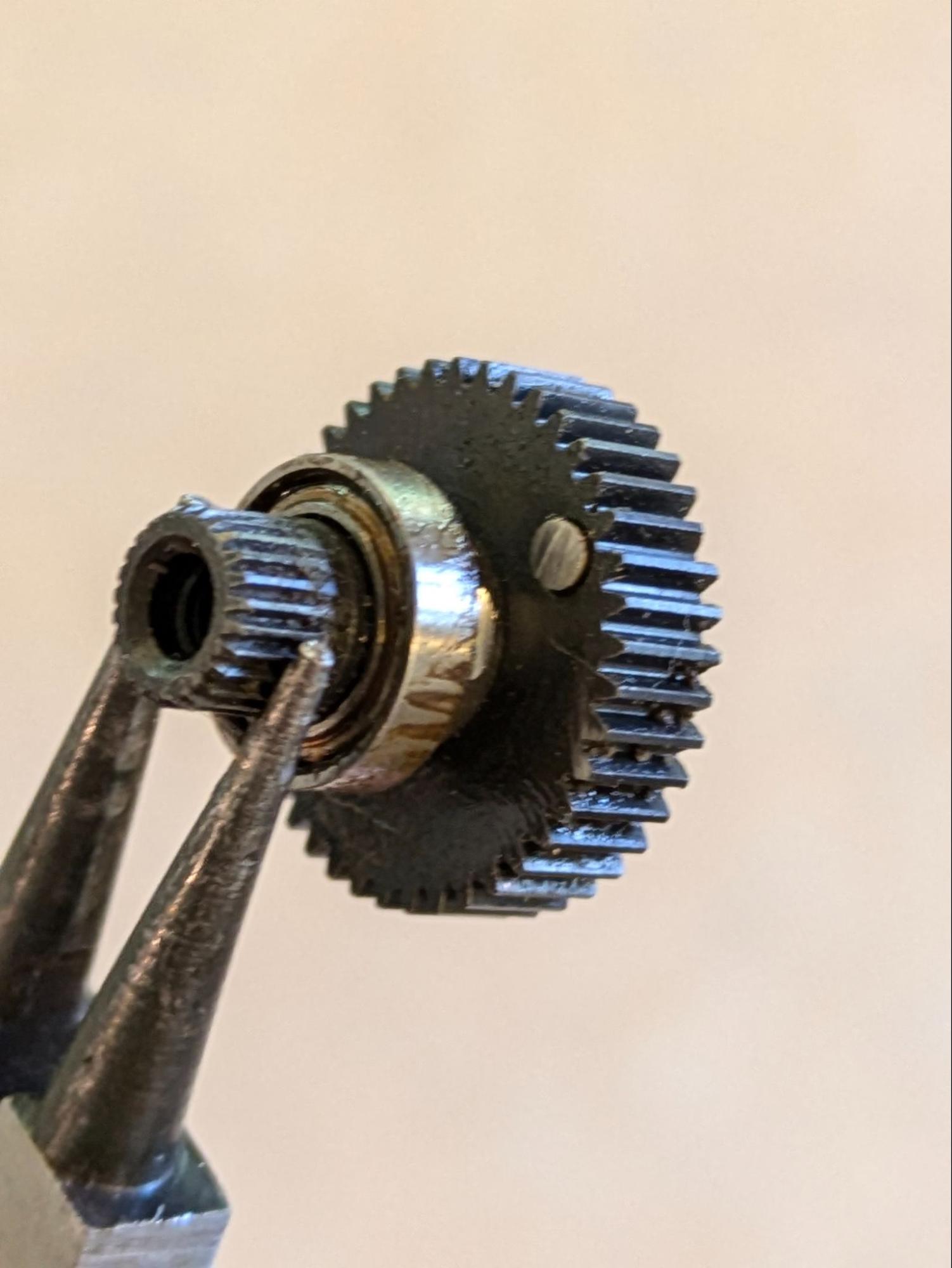 | The servo is typically limited by the small light-gray pin. In the photograph, you can see that we have ground it down with a dremel to remove the limit. Additionally, we have ground down the potentiometer and glued it in place. |
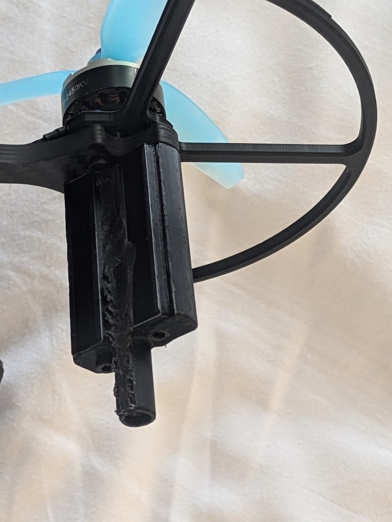
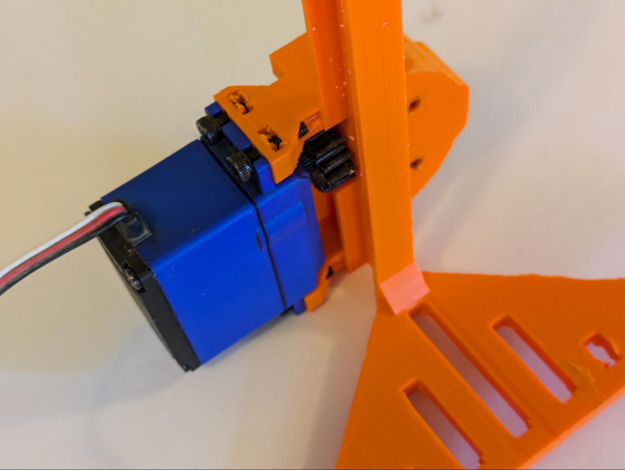 | The modified servo is attached to the gripper base, and a gear is attached to the servo spline. |
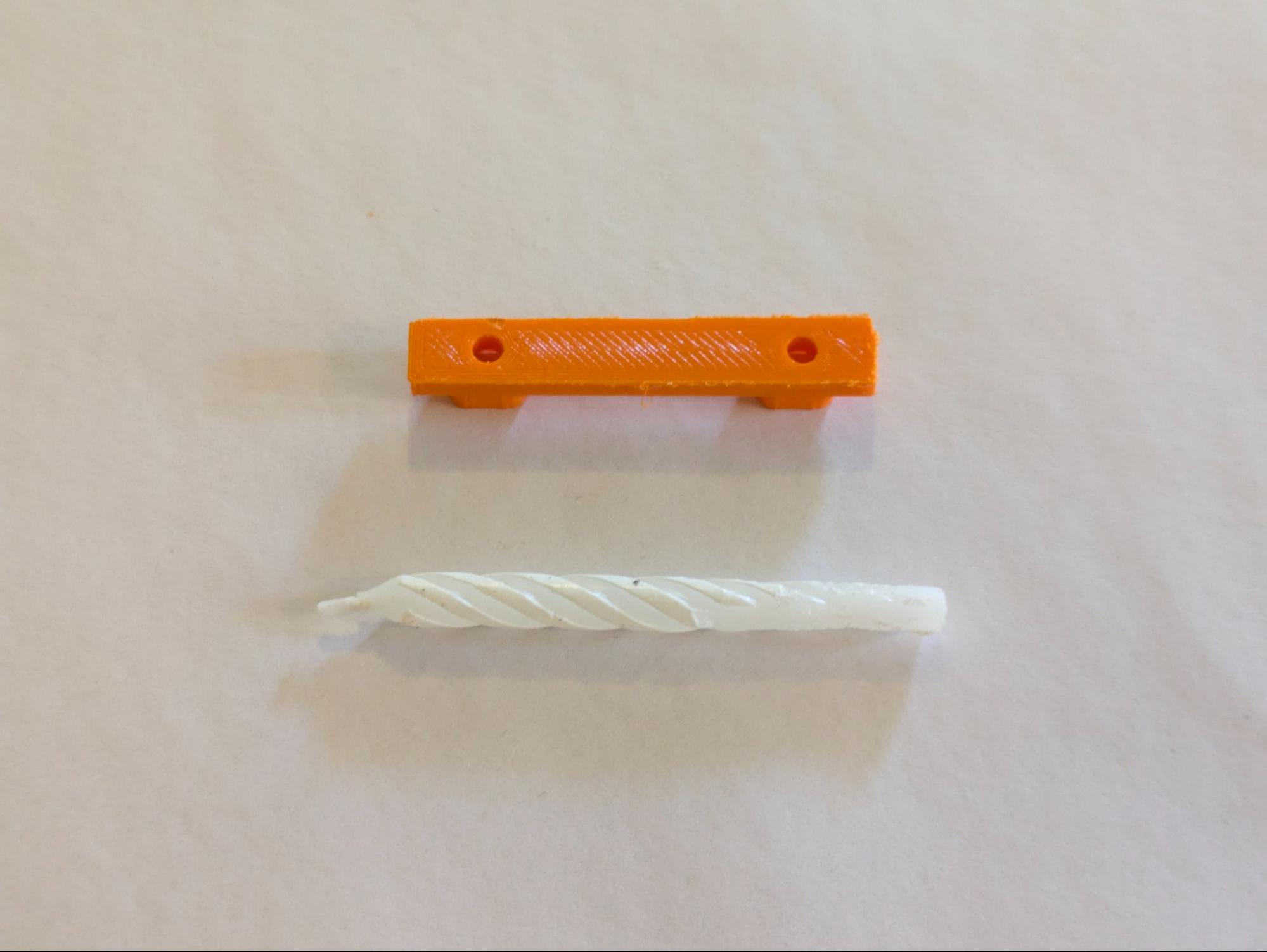 | Throughout the gripper’s construction, it is lubricated with candle wax for smooth operation. |
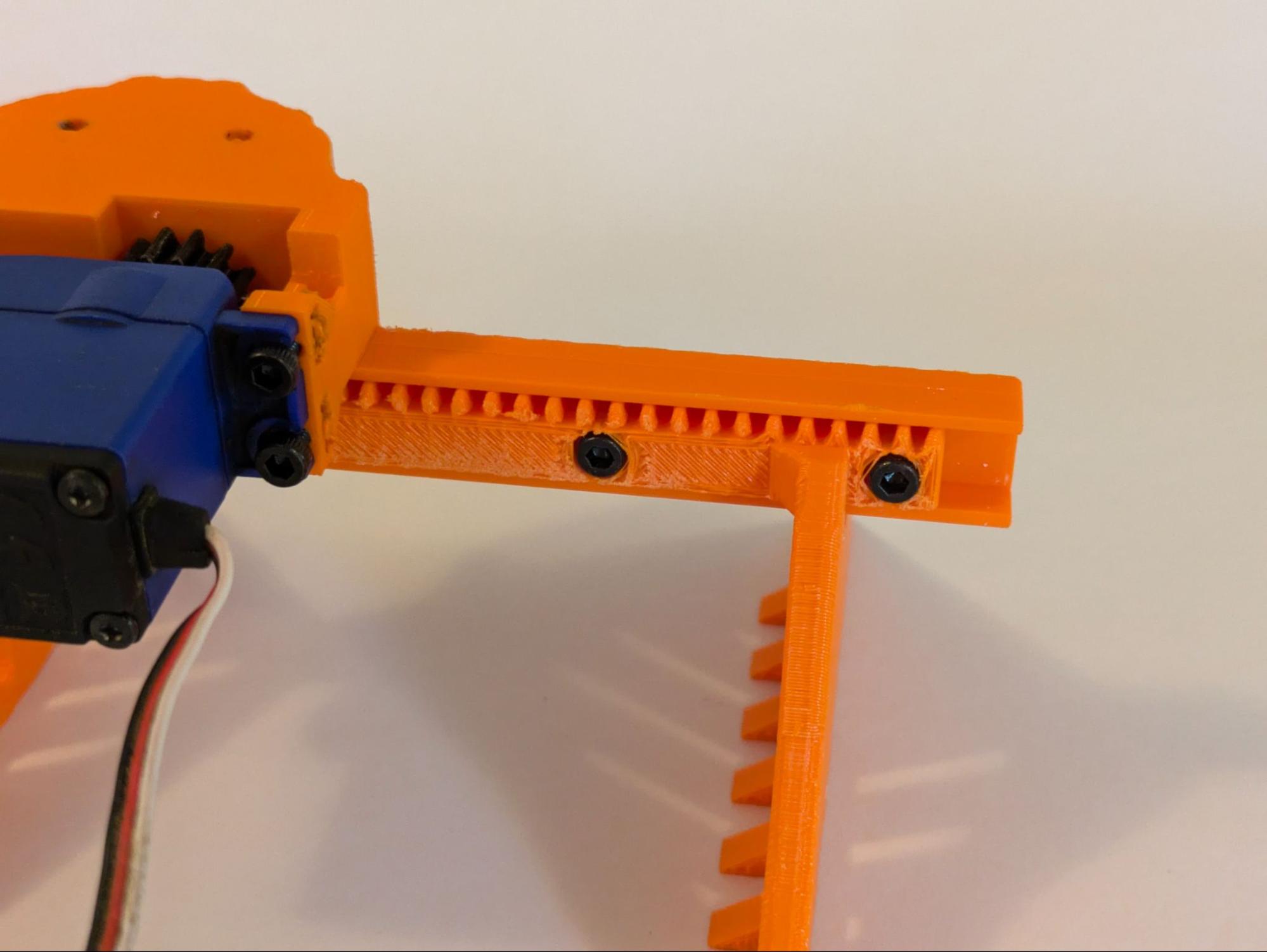 | The second half of the gripper and the rack is attached. |
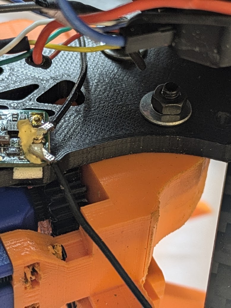 | The gripper assembly is attached to the middle plate of the quadcopter. Washers and nuts keep it in place. |
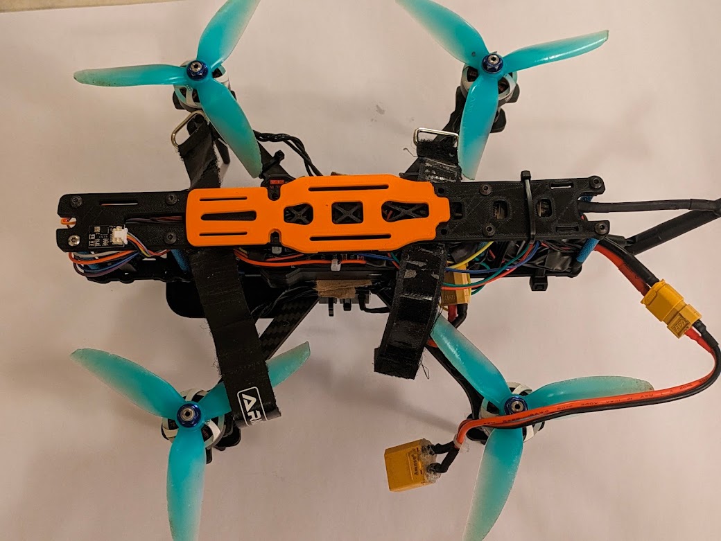 | The top plate is attached. The orange part on top of the plate is to prevent the battery from becoming punctured by the screws that go through the top plate. |
Wiring Schematic

ArduPilot
ArduPilot is an open-source piece of software that is used for flight control and autonomous navigation. This software runs on the Pixhawk. Our ArduPilot setup used a number of sensors for flight operations:
- Accelerometers, gyroscopes, and compasses: to understand its acceleration, speed, and changes in angle in a 3-dimensional space. These were built into the Pixhawk and did not have to be configured. One external compass was connected over I2C to keep it away from high-current, electromagnetically-noisy battery lines. All of those sensors were calibrated in Mission Planner for accuracy.
- LiDAR: to measure altitude from the ground. This sensor is placed facing down and times how long a beam of light takes to bounce off of the ground to measure the quadcopter’s height. This allows for accurate altitude control, enhancing control. The LiDAR sensor is connected over UART to the TELEM 2 port and configured in Mission Planner.
- Barometer: to measure air pressure to find altitude; is a backup to the LiDAR. However, the LiDAR is more accurate and is unaffected by propeller wash, unlike the barometer. If the LiDAR and barometer measure dramatically different altitudes, ArduPilot uses other sensors to determine which is most accurate. The barometer is built into the I2C compass module.
- Optical flow: to measure movement, essentially a camera pointed at the ground—like a computer mouse sensor. Our goal is to enable position holding—i.e. the ability to remove all controller inputs and have the quadcopter hover, motionless. This task requires precise location measurements, and accelerometers are not accurate on their own to accomplish this—they tend to drift. A GPS receiver would usually be required for position holding, but GPS does not work indoors. However, an optical flow sensor is, of course, able to operate inside and is capable of enabling position holding, increasing the quadcopter’s stability. The sensor is connected over UART to the SERIAL 4 port and configured and calibrated in Mission Planner.
There were two popular alternatives to ArduPilot that we considered and dismissed: BetaFlight and iNav. Betaflight is intended for racing drones, and, as such, it lacks the ability to use optical flow or LiDAR sensors and cannot hold altitude, much less position. On the other hand, iNav seemed very promising: It is very easy to configure, and the quadcopter flew well without tuning. However, iNav is less powerful and less configurable than ArduPilot. For example, it is impossible to take off in Position Hold mode in iNav. Instead, the pilot must take off in Altitude Hold mode and switch to Position Hold mode in the air, which is not a limitation in ArduPilot. This limitation creates a few hazardous seconds where the pilot is not fully in control. Additionally, iNav has worse hardware compatibility than ArduPilot. Therefore, ArduPilot was the best option for our quadcopter.
Still, Ardupilot led to some challenges. There were strong oscillations in-flight, and completing pre-arm checks was difficult. Oscillations were solved by turning down PID loop sensitivity, making the drone feel “floaty” but led to a controlled flight. ArduPilot normally looks for GPS, battery sensors, and more before allowing the pilot to arm. We disabled those checks because we are flying in a close space where those features are unnecessary. Finally, configuring all sensors took time but was doable with help from our resources.


Mission Planner
Ardupilot is configured through the use of parameters—hundreds of values that refer to specific settings. To configure something specific in ArduPilot, the user must edit one of those parameters. To tell ArduPilot that our optical flow sensor uses the MSP communications protocol, for example, we must set the RNGFND1_TYPE parameter to the value of 32, which internally represents MSP. This is where Ground Control Station—or GCS—software comes in. This software allows the user to easily change parameters in a human-readable format. Furthermore, many GCS software choices let the pilot view live telemetry data, access flight logs, and more. There are two primary GCS choices for Ardupilot: Mission Planner and QGroundControl. QGroundControl is cross platform and has a more user-friendly interface. However, its capabilities are more limited than Mission Planner, so we decided to use Mission Planner.
If we were operating with GPS, Mission Planner would let us create waypoints and define commands for autonomous use—but, of course, we aren’t performing those operations. However, Mission Planner still gives real-time telemetry data using the 3DR radio, which tracks the vehicle’s altitude, speed, battery voltage and draw, and sensor readings. Using this information, fine adjustments can be made to the drone using Mission Planner in conjunction with ArduPilot. Flight logs are also recorded for review later on, which can give us important insights about the drone’s behavior.
